LE2
A different approach to LED in darkroom enlargers
A project made by a photographer for the photographers
But designed by who has been electronics as a profession for more than 30 years
The story:
Given the umpteenth lockdown, an old electronic project is back in my hands, useful for photographer friends who still use the darkroom enlargers, chemicals, etc.
Today, those who engage in this hobby can find cheap darkroom magnifiers of all kinds, for black and white or for color photos, the latter usually with dichroic filters and powerful halogen lights (in many cases now unavailable).
More together the for old enlarger it was necessary to use big voltage transformers (and sometimes even a second 110V transformer...) all obsolete junk that in addition to consuming kilowatts can also be dangerous! in addition dichroic filters are badly adapted to the use with black and white, the restoration of these magnifiers with lamps and glass filters and timers can cost a lot, the final result is then not very usable...
Expecially the older color magnifiers, on the market on sale, as is, for parts or not working are the best deals cause their price is extremely low !
My idea is to use these kind of old darkroom-enlargers by renewing the electronics and adapting to our times!
The project is called "LE2" and it is the achronim of LED ENLARGER version 2 (yep it's an evolution of LE1!!!)
LE2 allows you to replace the magnifier light bulb, with high-efficiency LEDs that allow you to manage the light, contrast and density of the print that occurs simply by varying the percentages of color components RGB and UV.
The retrofit of the old enlarger must also include a precise timer and important options such as a darkroom magnifier exposure meter to correctly calculate the exposure time of the photo paper.
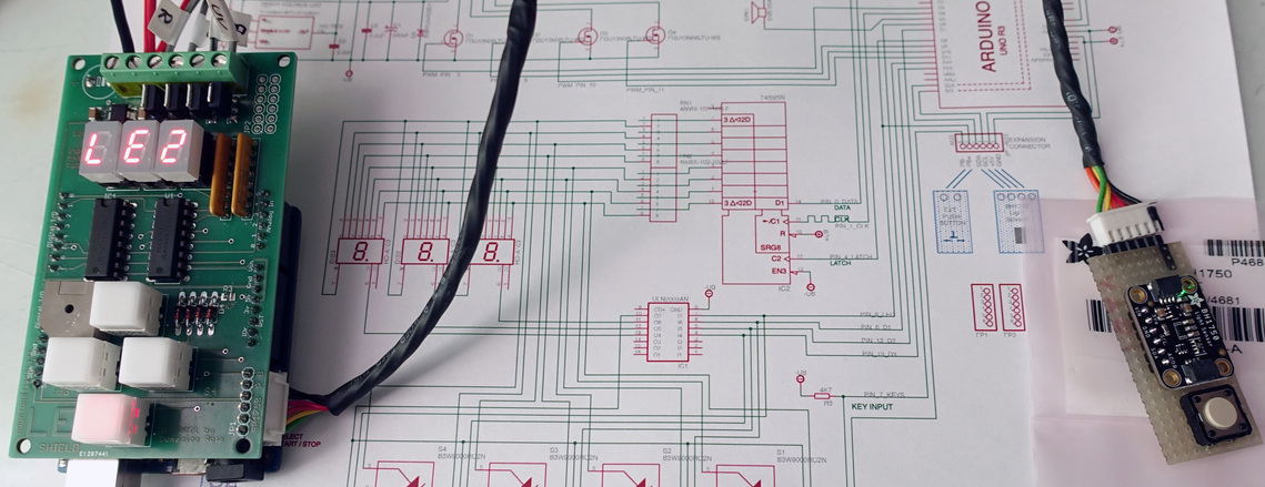
In the first version of 2012 the RGB LEDs had limited power and worked practically only at 12V, nowadays instead there are very sophisticated LEDs that use power supplies up to 48V, to facilitate the transformation of the magnifiers I have created an interface "SHIELD" for the mini controller ARDUINO UNO Rev3.
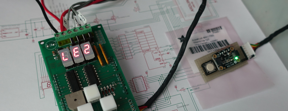
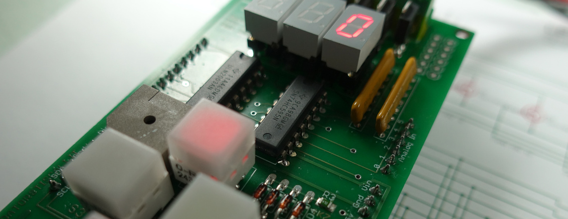
Basically it is an interface with a luminous keypad... luminous, because it gets dark in the darkroom!, A three digit 7-segment LED display and four N-channel Q-Fet that can manage practically all the power LEDs on the market.
To the initial prototipe, today I also added a high voltage LDO that allows you to use the most disparate DC power supplies (from 10V to 48V) the shield board in turn, powers the Arduino controller that contains the management program.
The news does not end there ... there is also a buzzer to emit sounds when attention is required, and, icing on the cake, also an i2c bus digital light meter.
In short, "LE2" allows You to have:
- LED light with selection of the desired DEGREE of contrast (filtration Grade)
- EXPOSURE TIMER from 0.1 to 600 Seconds!
- Start and stop of on-the-fly exposure for masking
- LIGHT MANAGEMENT:
- Focus (with WHITE light)
- Frame the photos without margin (using RED light)
- Selectable light output power
- SPOT light meter with automatic exposure calculation according to the type of light / negative / magnification chosen.
- Management of an external relay to use LE2 also with incandescent light bulb magnifiers (limited to use as a timer and darkroom exposure meter)
evrything on a 60x90mm electronic board !
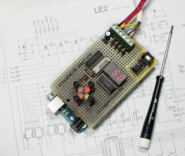
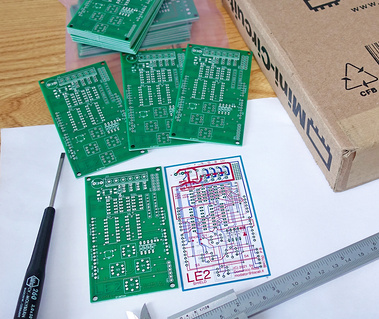
From prototype to the PCB
Yet another LED Controller for Darkroom enlargers ?
LE2 caratteristics
working for real in the darkroom I studied the best way to use LEDs with magnifiers for real, not just for play !
In circulation there are different types of this projects some spartans that do not have all the necessary functions, and some, that, instead of having required functions, only focus on graphic displays or alphanumeric LCD LEDs almost all they do not use UltraViolet LEDs, the worst uses complicated controllers with junk things that require tons of coding, library and waste of memory for doing fancy sounds and graphic on little displays, with rotary encoders simulating the old age magnifier controls, also the majority of them are limited to configurations with RGB LEDs only.
However, in this type of device you need more flexibility, you need to be able to use LEDs of every type and power, and also, why not, to use a relay that allows you to Connect a simple light bulb, for sure you need exposure meter, with digital adjustment and configuration memory, etc. etc. my decision was to start building the LE2 !
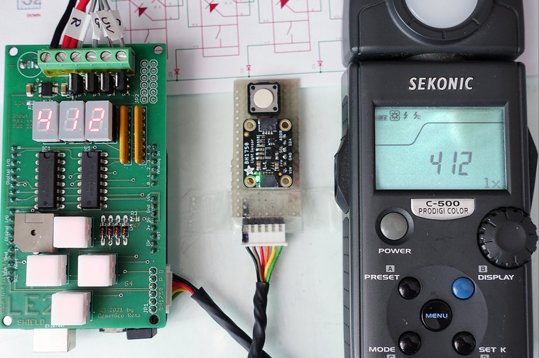
Luxmeter fuction of LE2 In comparison with a Sekonic C500 Prodigi Color
Key concepts
Original ideas
Using an Arduino Uno Rev3 for software implementation and concentrating on a different hardware specialized for the need.
Instead of using alphanumeric LCD or oled graphic matrix display I opted on a classic 7 segment three digit RED display, first because red light don't affect the paper, second because it's more readable expecially in the darkroom, plus also the four push button are lit with two LED each one (red + green) making posibe three colour, red, green and orange !
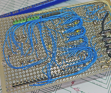
I study this system to combine the seven segment display , indication lights, push button and buzzer all together using only few wires of the controller, to do so everything is multiplexed using only a 74HC595 integrated circuit !
This serial to parallel shift register each scan pilots digit 0, digit 1, digit 2 and the 8 led (under the push button) for indications the line that goes to chip select is also passing trough the four push buttons permitting to read each one trough a diode matrix and a pull down resistor, using only a single input line to read all.
With this ingenious hardware, all the PWM / analog / lines are free to be used for the LED's, using four N-Channel Q-Fet that can stand current of 20 Amp, with proper dissipation it's possible to drive a load of near 100W per channel (the limit is the dimension of PCB traks, and the required dissipation...
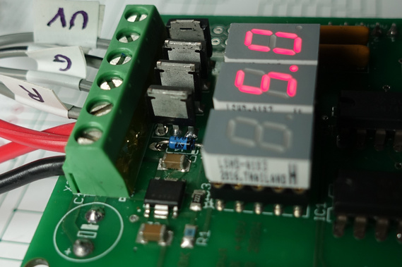
In the photos the output N Channel FET's are soldered all on component side without dissipator, in this configuration they can stand four 10W Led without problems.
Mounting this mosfets on solder side with copper blades heat spreaders permit to use a maximum of four 50W Led for a total of 200W ! (useful for very big enlarger up 10x12" and above).
Leaving a lot of resource to the little Arduino board permit to have them available for other interesting things, one is the buzzer that signals when the exposure is done, and the optional BH1750 Lux meter probe !
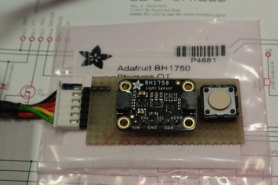
BH1750
The exposure meter is an optional, so the software is writed to detect if it is present and adapt the menu and functions !
When the exposure meter is available, at startup the LE2 emits a three beep sound, that signal the BH1750 was detected and the "rdL" and Lux functions are activated.
Taking in mind the exposimeter usage in the darkroom for real situation there is always the need to adjust the exposure according to paper / negative combinaton are used, to do so as the first exposure read and test is made, after the exposure reading the up / down push button become green, pushing them in this condition permit the photographer to adjust the exposure timing according his needs.
Once the exposure is adjusted it's easy to print the entire roll hassle free, with few other exposure reading only if the photo require it.
A closer look
Availability / BOM / Options / etc.
Wich one is right for you ?
This project permit a lot of flexibility , it's possible to have the PCB only, the PCB + parts to build it yourself, or LE2 allready made and tested, tailored with heat spreaders / optionals etc.
Warehouse at 13-05-2021 :
+ 1 LE2 Assembled & tested
+ 16 pieces of LE2 PCB Boards
+ 2 Set of conponents for complete LE2 with Lux Meter
+ 1 RGB 10W LED
+ 1 UV 10W LED
PCB + Manual + SW:
The PCB only option is the easyest, I can send the PCB with the bill of materials needed, a little operation manual and a link for download the binary file for the LE2 firmware. Perhaps this requires skills in SMD soldering (hot air station) Electronics components and schematic knowledge, but it's fantastic to construct it yourself !
I soldered my first LE2 in only 30 minutes of work !
A little video reviewing the LE2 Funtions !
Only for insiders...
The BOM for making LE2:
1x LE2-PCB-REVC Domenico Rota LE2 Project PCB board 60x100mm FR4 1,6mm thickness
4x B3W-9000-RG2N Omron Tactile Switches Illuminated Wh Cap 1 Red 1 Grn LED
3x LSHD-A103 Lite-On LED Displays & Accessories Red, Low Current 0.3", CCRHD
1x ULN2003AN Texas Instruments Darlington Transistors Array
4x 1N4148TA ON Semiconductor Diodes - General Purpose, Power, Switching Hi Conductance Fast
1x 1729160 Phoenix Contact Fixed Terminal Blocks 6P 5.08mm 90DEG
4x HMTSW-110-22-T-S-390 Samtec Board to Board & Mezzanine Connectors .100 High-Temp Variable Post Height Terminal Strip
2x C1206C225J5RECAUTO KEMET Multilayer Ceramic Capacitors MLCC - SMD/SMT 50V 2.2uF X7R 1206 5% AEC-Q200
1x CRGP0805F10K TE Connectivity Thick Film Resistors - SMD CRGP 0805 10K 1% SMD Resistor
1x RC0805JR-132K2L Yageo Thick Film Resistors - SMD 2.2 kOhms 250 mW 0805 5%
1x SG73S2ATTD4701F KOA Speer Thick Film Resistors - SMD 0.25W 4.7Kohm 1% 200ppm Anti-Surge
2x 4608X-102-102LF Bourns Resistor Networks & Arrays 8pins 1Kohms Isolated
1x S-1142BA0I-E6T1U ABLIC LDO Voltage Regulators IC REG LINEAR 10V 200MA
1x A750MV227M1HAAE020 KEMET Aluminium Organic Polymer Capacitors 50V 220uF 20% ESR=20mOhms
1x A000066 Arduino Development Boards & Kits - AVR Arduino Uno Rev 3
1x 4681 Adafruit Ambient Light Sensors Adafruit BH1750 Light Sensor - STEMMA QT / Qwiic
1x SN74HC595NE4 Texas Instruments Counter Shift Registers 8-Bit Shift Register
4x HUFA76429D3 ON Semiconductor MOSFET 20a 60V 0.027 Ohm Logic Level N-Ch
1x AST0540MW-03TRQ Mallory Sonalert Piezo Buzzers & Audio Indicator
1x MBR1100G ON Semiconductor Schottky Diodes & Rectifiers 1A 100V
1x HTY-1205000 LEDMO 12V 5A Power Supply 60W Transformer, Universal 12V Power Supply AC110-240V
1x PSP500JB-15R Yageo Wirewound Resistors - Through Hole 5W 15 Ohm 5%
1x SQP500JB-6R8 Yageo Wirewound Resistors - Through Hole 5W 6.8 Ohm 5%
1x 10W RGB LED chip (3W RED 3W GREEN 3W BLUE)
1x 10W UV 395nm LED chip (10W single chip)
At Your choice the LED type, but included in the BOM I suggest starting with two 10W LED (RGB + UV)
Optionals:
A little matrix Board (25x50mm) to use the BH1750 in conjunction with a push button of your choice to make a remote-like exposimeter, Cables 5 pole for the LED's, 5 pole plus shield flexible cable for the BH1750 board with push button, Power supply Red/Black cable.
Power supply consideration:
According to current needs of the two LED's, the proper power supply is to be chosen, better balancing the power using same voltage rating LED, I.E. 12V 10W LED's... that's suitable for most applications.
The maximum current of the LED is to be increased by a 50% to be sure our power supply (generally a switching) do not overheat !
For example for a solution of RGB 10W and UV 10V the real current is around 3,6A, s choosing a 5 Amps switching power supply is mandatory (also it's included in the BOM)!
Electronic compendium
For a project with RGB 10 W and UV 10W the LED voltage are different !
RED require a maximum of 7V ---> from 12V the dropdown resistor have to eat 5V, R = V/I = assuming I=330mA a 15 Ohm resistor is to be placed on the RED channel cathode, the power of the resistor is calculated P=IxV so a 5W resistor is suitable for this work...
GREEN require a maximum of 10 V ---> from 12V the dropdown resistor have to eat 2V, R = V/I = assuming I=330mA a 6 Ohm resistor is to be placed (I use a 6,8 Ohm 5W).
If arrived here maybe you are interested on the price of the components...
In general the total cost of the material, LE2 + EXPOSURE METER + RGB10W + UV10W + 12V 5A Power Supply is around 140€.
For LED dissipation and the mounted versions the price rises due to the time required for the construction and testing, availability, and shipping in a box instead of an envelope etc.
If interested please ask a quotation according your needs...
Domenico.